
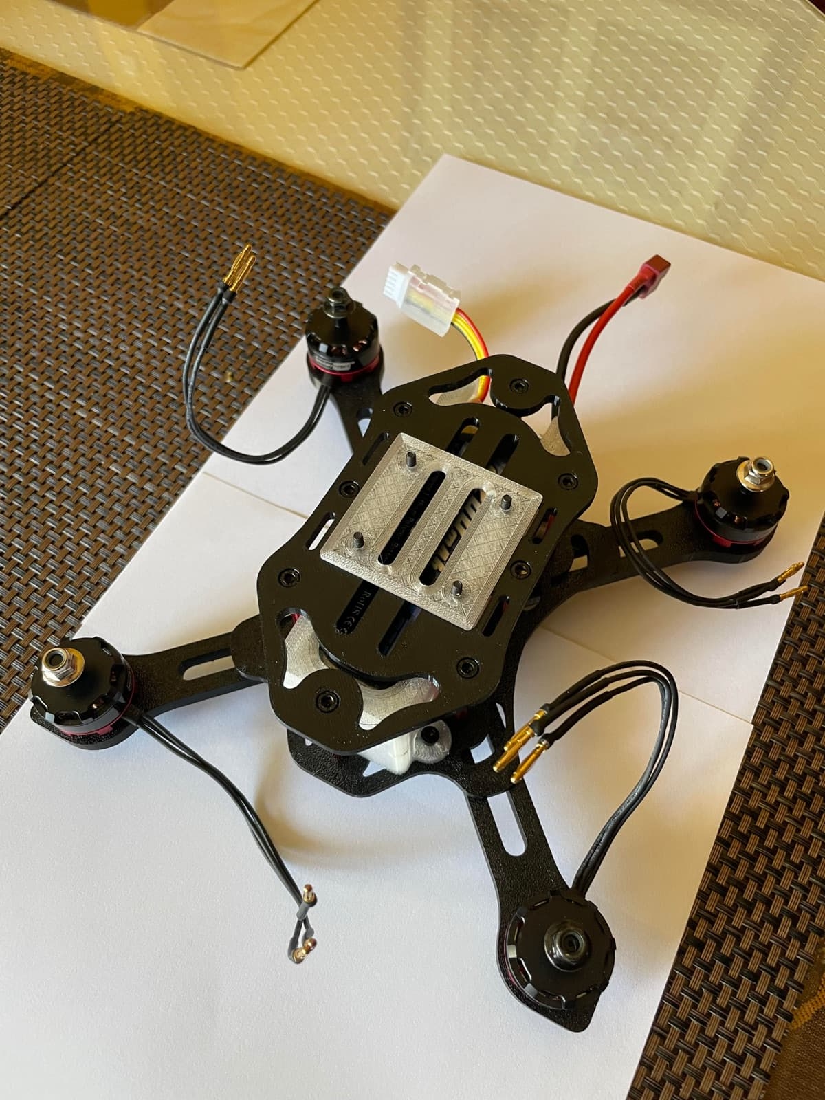
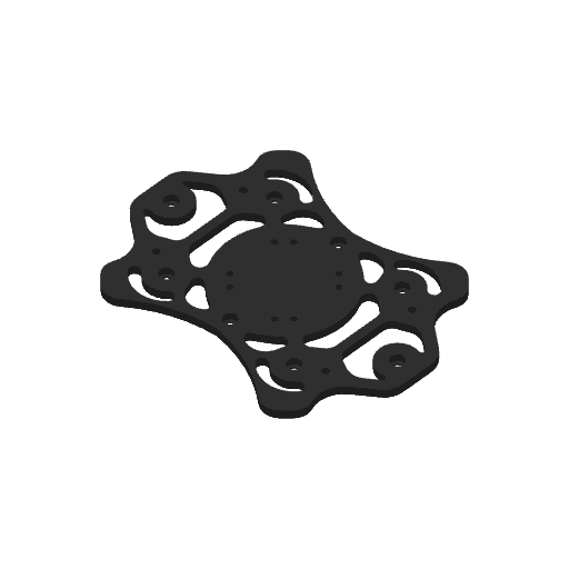
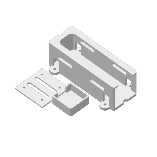
Bambu Lab P1S, 0.4 mm nozzle, 0.2 mm layers, 6 walls, 25% grid infill. From the Bambu Studio project files.
Next: validation
- Full-frame static FEArefined mesh at the arm rootsPlanned
- Modal analysisframe modes against motor excitationPlanned
- In-flight vibrationcorrelation with flight dataPlanned
- Timed field servicemodule swap time, repeated assemblyPlanned
Independent project
Scouting DroneA scouting drone has to fly efficiently, sense its environment, survive imperfect landings, and remain repairable outside the lab.
A from-scratch quadcopter frame in PETG and TPU, modeled in NX and printed on a Bambu Lab P1S.
Mass changes the system
Reducing structural mass lowers the thrust each motor must produce to hover.
Hover thrust equals weight. With the frame 29% lighter, the estimated all-up weight drops about 13%, and hover power falls with weight to the 1.5 power.
- frame-mass reduction
- 29%
- Iteration data
- estimated hover time on the 4S 2200 mAh pack
- ≈ 12.5 min
- Hand calculation
Momentum-theory estimate: about 723 g all-up (frame from CAD volumes), about 125 W to hover, 80% of the 32.6 Wh pack.
Carry the load
Motor thrust and landing loads enter at the arm tips and travel back into the center structure.
Material stays where bending peaks, at the arm roots. Weight-reduction slots sit farther out, where the bending moment is lower.
Tune the arm
The 17 mm × 6.8 mm arm section was tuned for stiffness-to-weight efficiency.
The built arm lies flat: 17 mm wide, with 6.8 mm in the bending direction. Bending stiffness grows with the cube of that depth, so how the section is turned matters as much as how much material it has.
- second moment of area as built, 6.8 mm in the bending direction
- 445 mm⁴
- Hand calculation
- higher if the same section stood on edge
- 6.25×
- Hand calculation
Section geometry only (I = b·h³/12). Root stress and tip deflection depend on the PETG modulus and load case; those values: future update.
Design for repeated loading
Vibration and imperfect landings make the arm root a fatigue-sensitive region.
The slot ends and the arm-root transitions are radiused to remove stress concentrations.
Build the center stack
The 40 mm aluminum standoff pattern creates clearance for electronics while increasing the torsional footprint of the center stack.
Aluminum, not printed plastic, where the stack is fastened again and again: it holds its dimensions, takes repeated assembly and separates the plates cleanly.
- standoff length, plate to plate
- 40 mm
- Design
- aluminum standoffs
- 8
- Design
Package the GPS
The GPS sits in a printed TPU mount at the top of the stack, clear of the frame and the electronics below it.
Sensing is a packaging problem too: a rigid location, a clear view of the sky, protection and access to the connector. The mount is TPU, printed in the same batch as the battery guard and stack plate.
Protect the motors
The motor interface carries thrust, but a TPU landing leg under each motor takes the landings and protects the motor in an impact.
Rigid PETG carries the loads; compliant TPU takes the hit, so the printed arm root and its load path are spared and a worn leg is simply replaced.
Manufacture and service
The frame was designed for additive manufacturing and for the person who has to repair it in the field.
- layers, 6 walls, 25% grid infill
- 0.2 mm
- Print settings
- bottom plate, printed flat
- No supports
- Print settings
PolyLite PETG for the frame and Bambu TPU 95A for the battery guard, GPS mount and stack plate, on a Bambu Lab P1S (from the Bambu Studio project files).
Analyze and validate
First-principles analysis established the stiffness trend; a 1 kg equivalent motor-load test checked whether the printed structure behaved predictably.
- equivalent motor load on an arm
- 1 kg
- Physical test
- and no permanent deformation after loading
- No cracks
- Physical test
- frame-mass reduction
- 29%
- Iteration data